| In this post I hope to explain how I built my first simple diy solar system, that I hope will eventually mean my entire garage can be powered off grid. Of course the system I'm going to show you here won't be powerful enough to completely run the garage's electricity requirements. This is simply, me learning about solar, the components involved, how they are connected and how the whole system behaves once installed.
|

|
|
Once I have learnt more about the system and how best to monitor performance, I will then upgrade some of the components, add sockets and lights etc. Initially I will be just happy to charge my mobile phone and perhaps the batteries for some of my power tools.
|
|
I started this project about 3 weeks ago, due to bad weather and the fact I had a cough, so I was unable to get out onto the hills, as I would normally do in my spare time. This seemed like an interesting project to get into and I had already seen other people doing a similar thing in their sheds or cabins. As I don't have a shed, I decided the garage would be the perfect location.
|
|
I made a start preparing the area that my system would be mounted and used scraps of wood from around the garage to create a control panel, battery bank and inverter shelf, plus an area for all my appliances to be plugged in to my free electricity source.
|
|
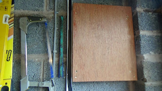
To create the control panel, I fixed 2 strips of 2" x 1" wood to the wall, then found a piece of marine ply, that I then cut to size and screwed into the strips on the wall. This created a void behind the panel to run all my wiring and fix terminal blocks, keeping the appearance of the finished panel neat and tidy.The panel is roughly a meter above the location of the battery bank.
|
|
To save space on the platform beneath my bench top, I decided to suspend a small shelf directly under the bench. This would keep the batteries nicely out of the way, leaving me ample room below for my inverter and associated sockets. Plus an area to charge all my appliances, such as mobile phone, battery drill, torches etc.
|

|
.JPG)
|
With a nice clear platform, I could now fashion an angled plinth, to mount my 4 gang 240v power strip, that was to be fed by the 400w 12v-240v inverter. The inverter would be located on yet another small shelf, beneath the battery bank, again neatly out of the way, but easy to access and operate.
|
|
The main structural work for the project was more or less complete, awaiting the arrival of my various components. First to arrive were the four 7ah sealed lead acid batteries, which I purchased off ebay for £27.00 (inc postage). I went for this initial battery arrangement as they are easy to handle and were relatively cheap.
|
|
To create a 12v 28ah battery bank I wired the batteries in parallel, using some relatively heavy duty wire and a terminal block. Initially I had the positive and negative feed coming off the last battery in the bank, but after watching a few videos and a bit of research, it seems the better option is take the positive from one end and the negative from the other (Which I have now done - see photo). This averages out the charge and discharge of the four batteries, rather than one of the batteries taking all the abuse.
|

|
|
With the battery bank now wired up, I moved them up onto their nice new shelf and wired the positive and negative leads into a terminal block, mounted on the leg of my bench, directly underneath the control panel.
|

|
Next item to be delivered by the postman was my Draper 400w 12v-240v inverter, which cost £18.00 (inc P&P) and that went straight onto its purpose built shelf, beneath the battery bank and was wired into the terminal block along with the feeds from the batteries. The cables in the flexible conduit goes upto an isolator switch, then continues on up to the control panel.
|
|
At this point I carried out a quick test of the inverter, by connecting up to the 4 gang power strip and plugging a small battery drill in to ensure it was charging ok... And it was... success !
|
|
|
Then, everything else I needed to complete the main part of the project, all came at once. The AKT 40w solar panel kit and 10A charge controller from Sunsprite Solar, plus an additional extension lead complete with MC4 connectors, that I would use to connect the solar panel into the charge controller without having to cut off the MC4 connectors. Plus a 6 way fuse board (£5.99) and 3 gang light switch (£2.66) With it still raining outside, I tucked myself away in the garage and set to work cabling up and fixing the various components to the control panel (which I have now sprayed a neat looking matt black).
|
|
I always like to work in my garage with the main door open, as it allows me to keep an eye on what's going on in the street, plus I can keep an eye on the kids whilst I'm working. But, as it was chucking it down with rain and I was quite obviously working with solar panels, I got quite few funny looks from dog walkers and people passing by, wondering what I was up to. They must of thought I was wasting my time, due to the conditions. But as I was to find out, even in poor weather conditions you will still produce some energy to trickle charge your battery bank, which in my mind is an added bonus.
|
|
|
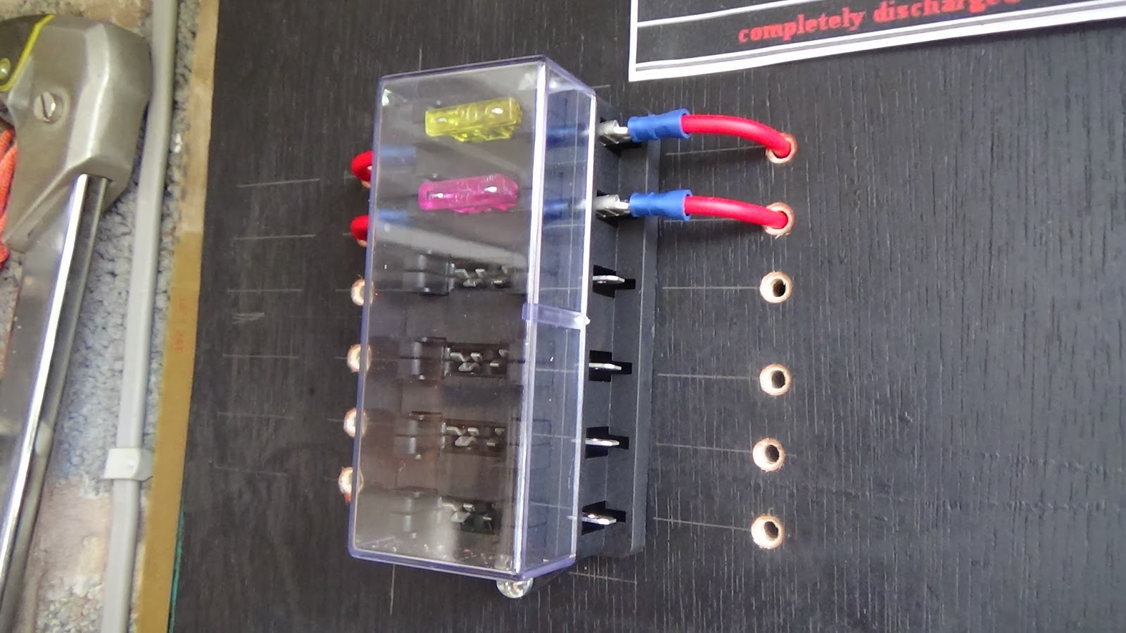
First to be mounted to the panel was the 6 way fuse board. I then drilled access holes to route the wires from the fuse panel to the back of the control panel, where the wires could then be distributed to the charge controller, solar panel, switches etc. I used cable crimps to secure the wires into the fuse panel.
|

|
|
Next up were the 3 gang light switch and the 10a charge controller. The charge controller was very easy to wire up, thanks to the simple diagrammatical instructions on the front of the controller and the robust terminals, which allowed for reasonably thick gauge wire. Again I used drilled access holes for the cabling to run behind the panel.
|

|

|
The last item to connect was the all important 40w AKT monocrystaline solar panel, complete with 5m fly leads and MC4 connectors. These would simply connect directly to the shorter lead that was already wired into the control panel, fuse board and switch. I was very impressed with the quality of this panel (even though I have never purchased one before, it just felt sturdy).
|
|
All that remained now was to switch everything on, check all the indicator lights were doing what they were supposed to be doing. Monitor the voltage with my meter, power up the inverter and try charging a few appliances with my free electricity. And do you know what ? It only bloomin' well worked !
|

|
|
What an interesting and rewarding little project this has turned out to be. I thoroughly enjoyed putting this simple home solar system together and have the guys at Sunsprite Solar to thank for their really informative website, which is full of great advice and tutorials to help solar newbies like myself get up and running in no time at all. I now look forward to adding extra features like LED lighting, volt meters, sockets etc. And ultimately I hope to go completely off grid in my garage. So please call back and see how I get on in the future, with my DIY simple home solar system.
|


.JPG)